
Rules to draw ray diagrams & sign convention rules for spherical mirrors


RULES TO DRAW RAY DIAGRAMS FOR SPHERICAL MIRRORS

                                                            Rule 1:

Mirror rule 1
The ray passing parallel to principal axis, after reflection passes through focus (or appears to be coming from focus in case of convex mirror)
Rule 2:
Mirror rule 2

The ray passing through Focus (or appears to be passing through focus in case of convex mirror), after reflection becomes parallel to principal axis.

                                            Rule 3:

Mirror rule 3

The ray passing through principal axis comes back in the same path after reflection.

                                          Rule 4:

Mirror rule 4 concave

Mirror rule 4 convex

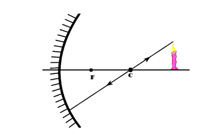
The ray passing through centre of curvature (or appears to be passing through centre of curvature) comes back in the same path after reflection.

Why the ray comes back in the same path after reflection in Rule 3 & Rule 4?

Tangent drawn to curvature

Because as we know the ray passing through normal to the surface comes back in the same path. So, any ray passing through centre of curvature is passing through normal to the spherical surface as it makes an angle of 900 with the tangent drawn to that point on the surface.


Note: the above rules are used to draw ray diagrams to understand the image formation by spherical mirrors. And the minimum number of rays required to show the formation of image is 2.

In ray optics

Object distance is denoted with ”u”

Image distance is denoted with “v”

Focal length is denoted with “f”

Radius of curvature is denoted with “R”.

Focal length is always half of the radius of curvature f=R/2 (or) R=2f

Sign convention rules for spherical mirrors:

i)                   All the distances must be measured from pole as pole acts as origin.

ii)                 The distances measured in the direction of incident rays are taken as positive and the distances measured in opposite direction to incident ray are taken as negative.

iii)               The heights measured above principal axis are taken as positive and the heights measured below the principal axis are taken as negative. 


thank you

Comments

Popular posts from this blog

REFRACTION THROUGH CURVED SURFACES (INTRODUCTION)

  BEHAVIOUR OF LIGHT WHEN IT ENTERS FROM ONE MEDIUM TO ANOTHER THROUGH CURVED SURFACES Let us try to understand how to draw ray diagrams in case of curved surfaces. We know that a ray of light passing from rarer to denser medium bends towards normal and   bends away to normal when it is passing from denser to rarer medium. So it is important to draw a normal to the curved surface.   Any line drawn from centre of curvature to a point on the surface acts like a normal to that surface because it makes an angle of 90 0   with the tangent drawn to that surface. Observe some examples of refraction of light through curved surfaces. Consider blue shaded region as denser medium. 1)1)     The ray passing from rarer medium to denser medium bends towards normal. 1)2)     The ray passing from denser to rarer medium bends away to normal. 1)3)    The ray passing along the normal(through centre of curvature) will not deviate from i...

prism and refractive index of prism

  PRISM:   A prism is a transparent medium separated from the surrounding medium by at least two plane surfaces which are inclined at a certain angle in such a way that, light incident on one of the plane surfaces emerges from the other plane surface. Consider a triangular glass prism. It contains  two triangular bases and three rectangular plane lateral surfaces. These lateral surfaces are inclined to each other. Let us consider that triangle PQR represents outline of the prism where it rests on its triangular base.       Let us assume that a light ray is incident on  the plane surface PQ of a prism at M as shown in figure. Draw a perpendicular to the surface at M. It becomes a normal to that surface. The angle between the incident ray and normal is called angle of incidence (i 1 ). The ray is refracted at M. It moves through prism and meets the other plane surface at N and finally comes out of the prism. The ray which comes out of the surfa...

Ohm's law, resistance and resistivity

 OHM’S LAW Before going to Ohm’s law let us discuss in brief about some electrical components or devices we use in electric circuits.    A Battery serves as a source of electricity in a circuit. We use mainly two measuring devices in this concept those are  Volt meter: used to measure potential difference between the two ends of a conductor. So it is always connected in parallel ( we learn about types of connections later in this chapter) Ammeter: used to measure the current passing in the circuit. So it is always connected in series. Now let us dive in to the activity did by Ohm to understand his concept. Materials required: 5 dry cells of 1.5V each, conducting wires, an ammeter, a volt meter, thin iron spoke of length 10cm, LED and key.   Procedure: Connect a circuit as shown in the above figure. Solder the conducting wires to the ends of the iron spoke. Close the key. Note the readings of current from ammeter and potential difference from volt meter in table ...